_Motore ad Acqua . Auto ad Acqua . Automobili a Miscela Idrogeno Ossigeno Carburante
_Vendita Kit di trasformazione Motore ad Acqua. Automobili a Miscela Idrogeno Ossigeno
_Biogas con Ossigeno, depurazione Acque Nere, di Fogna - Sistemi ad Arco Elettrico e Plasma - Magnegas
_Biogas, Rifiuti Liquami Scarti - Sistema a Fermentazione Biologica
_Auto ad Aria Compressa - Eolo e simili
_Sistemi ad Alta Efficienza - High Efficiency Systems
_Energia Libera - Terza legge della termodinamica
Questo credo che sia un metodo molto promettente da indagare per bene 
 A novel method of hydrogen generation by water electrolysis using an ultra-short-pulse power supplyVisualizza la prima pagine dell'articoloPULSED ELECTROLYSIS System, Shimizu & all
Journal of Applied Electrochemistry (2006) 36:419–423
Authors: Shimizu, Naohiro; Hotta, Souzaburo; Sekiya, Takayuki; Oda, Osamu1
Source: Journal of Applied Electrochemistry, Volume 36, Number 4, April 2006 , pp. 419-423(5)
Publisher: Springer--- Abstract: A novel method of hydrogen generation by water electrolysis using ultra-short-pulse power supply is demonstrated.
The ultra-short-pulse power supply consists of a static induction thyristor (SIThy) and a specific circuit which is called the inductive energy storage (IES) circuit. It was found that by using an ultra-short pulse with the width of 300ns, electrolysis takes place with a mechanism dominated by electron transfer, which is different from the conventional diffusion limiting process in DC electrolysis.
--- Introduction: It is possible to generate hydrogen by conventional DC water electrolysis, but this is undesirable for enviromental reasons if the electrical energy for the electrolysis is produced in thermal power stations from fossil fuel because of the generation of carbon dioxide. Fuel cells are promising and various systems are being studied worldwide. The generation of carbon dioxide during hydrogen generation through natural gas for fuel cells can be reduced compared with thermal power stations, but carbon dioxide is still generated. Hydrogen generation by photo-catalysis is preferable but the process efficiency is still very low for practical applications.
Recently, water electrolysis has been reconsidered as a promising method for hydrogen generation since the cost of electricity is decreasing, mainly as a result of wind-generated power. Hydroelectricity and nuclear power can be also used for water electrolysis without generation of carbon dioxide. Even though the electricity cost is falling, it is known that the plant cost for water electrolysis by DC power still dominates a large part of the hydrogen production cost. It is therefore desirable to find a new method of generating hydrogen from water at lower cost. In the present work, we have examined for the first time the applicability of an ultra-short-pulse power supply for water electrolysis.
--- Principle: In the conventional DC electrolysis of water, hydrogen is generated as a result of electron transfer from the cathode electrode to adsorbed hydrogen ions on the electrode surface. This electrolysis occurs when the applied voltage between the anode and the cathode exceeds the water decomposition voltage of about 1.6V, the sum of the theoretical decomposition voltage of 1.23V at room temperature and the overvoltage of about 0.4V depending on electrode materials and other factors[1]. DC electrolysis is a diffusion limited process and the current flow in water is determined by the diffusion coefficient of ions. It is therefore difficult to increase the input power for a constant volume electrochemical cell without reduction in electrolysis efficiency.
We have applied an ultra-short pulsed power supply based on a static induction thyristor (SIThy), invented by Nishizawa et al. [2,3] and developed by Shimizu et al. [4,5], and an inductive energy storage (IES) circuit invented and developed by Iida et al. [6,7] and applied in several ways by Jiang et al. [8]. SIThys are Si devices with special structures for high power pulse generation and IES circuits are small-scaled circuits based on induction storage instead of conventional capacitor storage in order to use SIThys. We have applied SI thyristors developed in our laboratory to water electrolysis and found that water electrolysis occurs by a different mechanism from the conventional DC one.
When the ultra-short pulse voltage of less than seceral microseconds is applied to a water electrolysis bath, the voltage application is so fast neither the electric double layer nor the diffusion layer can be stably formed in the vicinity of electrodes.
The pulse width which is necessary for electrolysis without formation of the diffusion layer is estimated [9] to be:
Del.t<(1/4D).(Xad/X)2 (1)
Here, Del.t is the pulse width (s), D the diffusion coefficient (cm2 s-1), Xad the density of hydrogen ions on the cathode electrode (cm-2) and X (cm-3) is the concentration of hydrogen ions in the solution. This equation was simply calculated under the assumption that the total amount of adsorbed ions, Xad, is equal to the diffusion layer thickness d (cm) multiplied by X, and d must be larger than the diffusion length (4D Delt.t)1/2 during the pulse application, considering that the pulse application duration must be shorter than the time necessary to fill the diffusion layer with hydrogen ions. From this equation, taking as D=2.3x10⁻⁵ cm2 s-1 for proton diffusion coefficient [1], X=6x1020 cm-3 for 1M for KOH solution and Xad=1015 cm-2 for platinum metal surface, the pulse width is estimated to be about 3 microsecond. This means that electrolysis occurs without forming the diffusion layer in the present work since the pulse width is one tenth of this critical 3 microsec.. It is also known that the time necessary for the formation of the stable electrical double layer is of the order of several tens of milliseconds [1]. It is therefore evident that the stable electrical double layer is not formed during the present ultra-short pulse application. Since an electric field as high as 2.6-47V cm-1 can be applied in the present work, the lack of formation of the stable electric double layer means that hydrogen ions can be moved faster than in conventional DC electrolysis. These different mechanisms that arise via ultra-short pulse application, leading to the absence of the diffusion layer and the stable electrical double layer, mau open the possibility of high capacity water electrolysis.
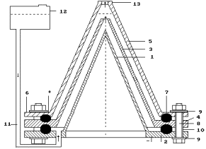
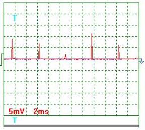
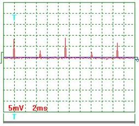
--- Experimental: In order to examine the possibility of water electrolysis by ultra-short pulses, 3.41 of 1M KOH solution were put in an electrolysis bath. 3.3x9cm2 platinum plates were used as the anode and cathode. The distance between electrodes was set as 3 cm. The solution temperature was kept at 293 +-2 K during the experiment. A conventional DC power supply and an ultra-short pulse power supply were used for comparison. The ultra-short pulse power supply consisted of the IES circuit with a SIThy as shown in Figure1. Ultra-short pulses with a voltage pulse-width of about 300ns, with the secondary peak voltage rangin from 7.9 to 140V were applied to the electrochemical bath with the frequency of 2-25 kHz. The input power was changed by increasing the pulse frequency.
In the IES circuit (Figure1), the gate of the SIThy is connected to the anode through a diode. When the FET (Field Effect Transistor) is switched on, the current through the inductive coil (L1) gradually increases. When the FET is switched off at a certain current level, the current flow is instantly switched off and the inverse voltage Vp1 is induced through the coil (L1). This IES circuit is the simplest and most compact one yet reported for generating ultra-short pulses [6-8].
Fig.1. Ultra-short pulsed power supply circuit for water electrolysis based on the inductive energy storage (IES) circuit [6-7] with a static induction thyristor (SIThy).
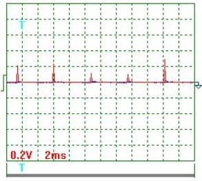
In the case of water electrolysis using the above ultra-short pulse power, the water bath electrodes are connected to the secondary reactance L2 as seen in Figure1. The pulsed voltage V
p2 is induced in the secondary reactance L2, synchronized with the pulsed voltage V
p1 as seen in Figure2. In the first stage, when this secondary pulsed voltage is applied to the electrodes in the water bath,
the bath acts as a quasi-capacitor since the pulse width is too short for ions in the bath to cause a current through the bath. This gives a very short pulsed current I
p2 in the circuit through the secondary coil (L2). This current is too rapid to be seen in the figure. The water bath is not a real capacitor since all electrons collected at the cathode are transferred to hydrogen ions and high voltage does not remain as in the case of conventional capacitors. After this pulsed voltage had been applied to the electrolysis bath, in the second stage, the current I2 flows through the circuit. This current flows very slowly as seen in the figure with several tens microseconds. Since the application of the pulsed voltage V
p2 was already terminated, this current flow I2 may not be due to electron transfer to hydrogen ions but ion transport in the bath, thus compensating the lack of hydrogen ions in the vicinity of the cathode electrode.
--- Results and discussion: The hydrogen generation rate and its efficiency are plotted as a function of the input power between the electrodes in Figure3. In the case of DC power electrolysis, when the applied voltage is increased, the current increases so that hydrogen generation rate increases, but the efficiency compared with the ideal generation rate decreases
from 40% at 2.2V to 8% at 12.6V. Here, the ideal generation rate was calculated from thermodynamical data [10], for the thermodynamical energy for hydrogen to be converted to room temperature water. The decrease in efficiency can be explained because an electron with high energy can only reduce one hydrogen ion so that the difference between the applied voltage and the decomposition voltage is dissipated as heat. Since the current itself is also increased by increasing the applied voltage, electrons which are not used for hydrogen reduction are also dissipated as heat.
Contrary to the case of DC power electrolysis, ultra-short power electrolysis shows a quite different behaviour. As seen in Figure3(a), in the case of DC electrolysis, the hydrogen generation rate was not proportional to the input power. It deviates from the ideal line. The hydrogen generation efficiency is calculated as the ratio of the real generation rate to the ideal hydrogen generation rate and it can be seen in Figure3(b) that the efficiency is largely decreased in the case of DC electrolysis. This decrease is mainly because the energy of most electrons is dissipated as heat.
In the case of pulse power, it is seen in Figure3(a) that the hydrogen generation rate is increased as the peak voltage is decreased. It should be noted, however, that the hydrogen generation rate increases as a function of the input power. This behaviour is quite different from the case of DC electrolysis. When the input power is increased by increasing the pulse frequency, the efficiency was not decreased in the case of high peak voltages, and was increased in the case of low peak voltages as seen in Figure3(b).
This behaviour is contrary to the case of DC power. This increase of the efficiency for the case of low peak voltage may be because the energy dissipation is decreased since each electron has lower energy and the pulse waveform is sharper for low peak voltages. For these reasons, power can be efficiently consumed for electrolysis. This fact implies that the ultra-short power electrolysis is a promising method in which the power application can be increased even with an increase in electrolysis efficiency.
In the case of DC power, the electric field is always present. The electrical double layer is also present and the diffusion layer always exist. The current flow is therefore determined by the diffusion of ions with a driving force of ion concentration difference. When the applied voltage is increased, the efficiency decreases. In the cse of DC power, the power applicable for a certain volume of the electrolysis bath is therefore limited.
www
Fig.2. A typical example of pulse waveforms for the first and second stages. In the first stage, an ultra-short pulse with the width of about 300ns is applied. In the second stage, the current flows slowly.

Fig.3. Hydrogen generation rate (a) and its efficiency (b) as a function of the input power. In the case of pulsed power, various circuits with different voltage (Vp2), current (I2max) and frequency ((i)-(iv)) have been compared. The input power is the integration of the secondary voltage and current multiplied by the frequency. The ideal line was calculated from the thermodynamical energy for hydrogen to be converted to room temperature water. Hydrogen generation efficiencies in (b) were calculated as the hydrogen generation rate divided by the ideal hydrogen generation rate at the same input power.
In the case of ultra-short pulsed power, the electric field is applied for only a very short time less than several microseconds which is much shorter than the time necessary for the formation of the constant electric double layer.
By the application of the ultra-short pulse, electrons are collected on the surface of the cathode electrode as in a capacitor. The electrons gathered however are quickly transferred to hydrogen ions for hydrogen generation so that electrons do not remain in the electrode as in a conventional capacitor. After this electron transfer, the current I2 flows slowly as shown in Figure2, probably due to the ion diffusion in the electrolysis bath.
From the above considerations, it can be concluded that the electrolysis mechanism for ultra-short pulse power is very different from that of DC electrolysis. DC electrolysis is based on electrical double layer formation and is a diffusion-limited process, while ultra-short pulse power electrolysis is based on the strong electric field application and the electron transfer limited process. This difference seems to be very important for the practical and industrial application of ultra-short power electrolysis since the electrolysis power can be increased without decreasing the efficiency.
--- Conclusion: We have shown in this preliminary work how an ultra-short power supply, consisting of a SIThy and an IES circuit, can be applied to water electrolysis for hydrogen generation. It has been found that an ultra-short pulse of about 300ns could generate hydrogen gas. It was also found that power could be increased without decreasing the electrolysis efficiency. The present results point to the possibility that water electrolysis by ultra-short pulsed power occurs under the electron transfer-rate limiting mechanism, which is different from the conventional diffusion-limiting mechanism in DC power electrolysis.
--- Ackonledgements: We thanks Messrs S. Ohno and T. Inaba for their encouragement of this work, Mrs K. Matsuhiro, Y. Imanishi and S. Tange for their helpful discussion, and Mr M. Imaeda for his experimental help.
--- References:
1 - T. Watanabe and S.Nakamura, Introduction to Electrochemistry: Chemistry of Electron Transport (Japan Chemical Society, 1996)
2 - J. Nishizawa, T. Teriyaki and J. Shibata, Res. Inst. Electrical Comm. Tohoku Univ. Tech. Rep., RIEC TR-36 (1973) 1.
3 - J. Nishizawa, T. Teriyaki and J. Shibata, IEEE Trans. Electron Dev., ED-22 (1975) 185.
4 - N. Shimizu, K.-S. Lee, M. Yuri, Y. Ikeda and K. Murdock, Proc. 10th Symp. Static Induct. Dev., SSID-97-6 (1997) 29.
5 - R. Hironaka, M. Watanabe, E. Hotta, A. Okino, M. Maeyama, K.-C. Ko and N. Shimizu, IEEE Trans. Plasma Sci. 28 (2000) 1524.
6 - K. Iida and T. Sakuma, Proc. 15th Symp. Static Induct. Dev., SSID-02-9 (2002) 45.
7 - N. Shimizu, T. Sekiya, K. Iida, Y. Imanishi, M. Kimura and J. Nishizawa, Proc. Int. Symp. Power Silicon. Dev. (ISPSD) P-30 (2004) 281.
8 - W. Jiang, K. Yatsui, K. Takayama, M. Akemoto, E. Nakayama, N. Shimizu, A. Tokuchi, S. Rukin, V. Tarasenko and A. Pachenko, Proc. IEEE 92 (2004) 1180.
9 - O. Oda and N. Shimizu, Japan Patent Pending, 2004-223595.
10 - O. Kubaschewski, E.L. Evans and C.B. Alcock, Metallurgical Thermochemistry (Pergamon Press, 1967).
Come si vede da questi test realizzati dal gruppo di Shimizu, l'elettrolisi a 12 volts Viola non e' per nulla efficiente anche se produce idrogeno e ossigeno in quantita'. Infatti si vede dal grafico dell'efficienza, dove l'efficienza e' calcolata come il rapporto tra tasso di generazione misurato nell'esperimento, rispetto al tasso ideale di generazione a parita' di energia impiegata.
mentre per quanto riguarda l'efficienza dell'elettrolisi industriale usata al giorno d'oggi, ovvero nel grafico (a) l'ultimo puntino giallo ( 2.2V - 0.2A ), rispetto all'elettrolisi ad impulsi (Verde a 17 kHz ), si ha : |
................ Energia ... Idrogeno ... Watt x Idrogeno
................ Watt ...... Cm3 sec-1 .. ?W ...........
......................................... x1 Cm3 sec-1
Elettrolisi DC
Industriale .... 0.35 ...... 0.018 ...... 19 W
2o punto ....... 1.1 ....... 0.060 ...... 18
3o punto ....... 2.9 ....... 0.110 ...... 26
4o punto ....... 5.6 ....... 0.200 ...... 28
5o punto ...... 11.0 ....... 0.310 ...... 35
6o punto ...... 25.0 ....... 0.600 ...... 42
7o punto ...... 77.0 ....... 1.100 ...... 70
8o 12.6V 20A . 240.0 ....... 2.200 ..... 109
Elettrolisi Impulsi
1o .. 7.5 kHz .. 0.65 ...... 0.025 ...... 26 W
2o . 15 . kHz .. 1.0 ....... 0.041 ...... 24
3o . 17 . kHz .. 1.03 ...... 0.064 ...... 16Ovvero l'elettrolisi ad impulsi di 300 nano secondi e' piu' efficiente di quella in corrente continua a partire da circa 15000 impulsi al secondo, piu' o meno il punto di incrocio tra le due curve. Resta da vedere quanto efficiente sarebbe aumentare il numero degli impulsi ad esempio a 30000.
Dal grafico (b) si capisce un'altra cosa importante: Passando dal test a 62V al test a 9.7V si nota una inversione di flessione della curva all'aumentare del numero di impulsi al secondo. Ovvero man mano che si diminuisce la tensione agli elettrodi, si arriva ad una tensione critica, al di sotto della quale, l'aumentare degli impulsi per secondo produce un'aumento di rendimento invece che una diminuzione.
Quindi esistera' un fenomeno non menzionato che mangia energia senza produrre scissione dell'acqua, la percentuale di energia mangiata aumenta con l'aumento della tensione applicata.
Guardando l'evoluzione dei test da 140V a 7.9v, e' molto probabile che un test ad esempio a 3V, potrebbe fornire un rendimento elevatissimo con una potenza sempre al di sotto di 1 watt !
Ultima faccenda evidente e' che le curve di rendimento per potenza tra elettrolisi ad impulsi e a corrente continua si incrociano invece che affiancarsi, quindi:
- In CC aumentando la tensione, diminuisce l'efficienza,
- Ad impulsi aumentando la frequenza degli impulsi, aumenta l'efficienza. |
Edited by fabrizio3 - 4/4/2010, 10:28